Tetris in SPARK on ARM Cortex M4
by Tristan Gingold , Yannick Moy –
Tetris is a well-known game from the 80's, which has been ported in many versions to all game platforms since then. There are even versions of Tetris written in Ada. But there was no version of Tetris written in SPARK, so we've repaired that injustice. Also, there was no version of Tetris for the Atmel SAM4S ARM processor, another injustice we've repaired.
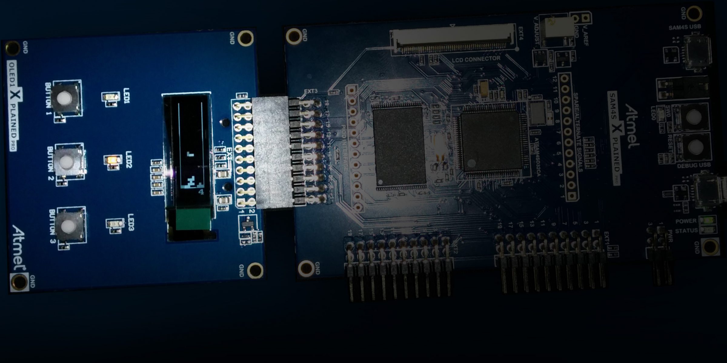
The truth is that our colleague Quentin Ochem was looking for a flashy demo for GNAT using SPARK on ARM, to run on the SAM4S Xplained Pro Evaluation Kit of our partner Atmel. Luckily, this kit has an extension with a small rectangular display that made us think immediately of Tetris. Add to that the 5 buttons overall between the main card and the extension, and we had all the necessary hardware.
Now, how do you make a Tetris in SPARK for ARM? First, the ingredients:
- a SAM4S Xplained Pro Evaluation Kit + OLED1 Xplained Pro extension + Atmel manuals
- GNAT GPL 2014 for ARM
- a recent wavefront of SPARK Pro 15.1 (*)
- the WikiPedia page describing Tetris rules
- a webpage describing the Super Rotation System (SRS) for Tetris
- an engineer who knows SPARK
- an engineer who knows ARM
(*) If you don't have access to SPARK Pro 15.1, you can use SPARK GPL 2014, but expect some differences with the verification results presented here.
Count 2 days for designing, coding and proving the logic of the game in SPARK, another 2 days for developing the BSP for the board, and 0.5 day for putting it all together. Now the detailed instructions.
The whole sources can be downloaded in the tetris.tgz archive attached.
A Core Game Logic in SPARK
SPARK is a subset of Ada that can be analyzed very precisely for checking global data usage, data initialization, program integrity and functional correctness. Mostly, it excludes pointers and tasking, which is not a problem for our Tetris game.
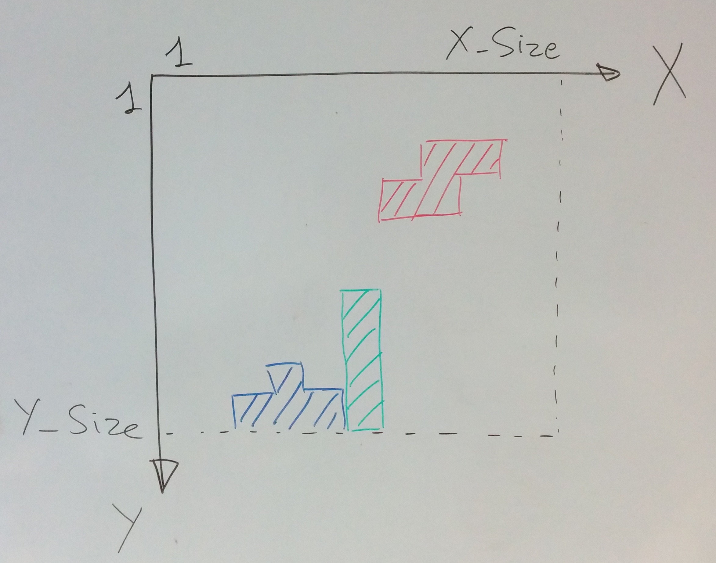
We modeled the display (the board) as an array of Y_Size lines, where each line is an array of X_Size cells, and the origin is at the top left corner:
A cell is either empty, or occupied by a piece in I, O, J, L, S, T, Z (the name of the piece hints to what form it takes...), and the piece falling as a record with the following components:
- a shape in I, O, J, L, S, T, Z
- a direction (North, East, South or West) according to SRS rules
- a pair of (X,Y) coordinates in the board, corresponding to the coordinate of the top-left cell of the square box enclosing the piece in SRS
Two global variables Cur_Board and Cur_Piece store the current value of the board and falling piece. Finally, SRS rules are encoded in Boolean matrices defining the masks for oriented shapes (where True stands for an occupied cell, and False for an empty cell).
All the above can be expressed straightforwardly in SPARK as follows:
--  possible content of the board cells
type Cell is (Empty, I, O, J, L, S, T, Z);

--  subset of cells that correspond to a shape
subtype Shape is Cell range I .. Z;

--  subset of shapes that fits in a 3 x 3 box, that is, all expect I and O
subtype Three_Shape is Cell range J .. Z;

--  the board is a matrix of X_Size x Y_Size cells, where the origin (1,1)
--  is at the top left corner

X_Size : constant := 10;
Y_Size : constant := 50;

subtype X_Coord is Integer range 1 .. X_Size;
subtype Y_Coord is Integer range 1 .. Y_Size;

type Line is array (X_Coord) of Cell;
type Board is array (Y_Coord) of Line;

Cur_Board : Board;

--  the current piece has a shape, a direction, and a coordinate for the
--  top left corner of the square box enclosing the piece:
--    a 2 x 2 box for shape O
--    a 3 x 3 box for all shapes except I and O
--    a 4 x 4 box for shape I

subtype PX_Coord is Integer range -1 .. X_Size - 1;
subtype PY_Coord is Integer range -1 .. Y_Size - 1;

type Direction is (North, East, South, West);

type Piece is record
   S : Shape;
   D : Direction;
   X : PX_Coord;
   Y : PY_Coord;
end record;

Cur_Piece : Piece;

--  orientations of shapes are taken from the Super Rotation System at
--  http://tetris.wikia.com/wiki/SRS
--    shape O has no orientation
--    shape I has 4 orientations, which all fit in the 4 x 4 box
--    shapes except I and O have 4 orientations, which all fit in the 3 x 3 box

--  Note that Possible_I_Shapes and Possible_Three_Shapes should be accessed
--  with Y component first, then X component, so that higher value for
--  Direction correspond indeed to clockwise movement.

subtype I_Delta is Integer range 0 .. 3;
type Oriented_I_Shape is array (I_Delta, I_Delta) of Boolean;
subtype Three_Delta is Integer range 0 .. 2;
type Oriented_Three_Shape is array (Three_Delta, Three_Delta) of Boolean;

--  orientations for I

Possible_I_Shapes : constant array (Direction) of Oriented_I_Shape :=
  (((False, False, False, False), (True,  True,  True,  True),  (False, False, False, False), (False, False, False, False)),
   ((False, False, True,  False), (False, False, True,  False), (False, False, True,  False), (False, False, True,  False)),
   ((False, False, False, False), (False, False, False, False), (True,  True,  True,  True),  (False, False, False, False)),
   ((False, True,  False, False), (False, True,  False, False), (False, True,  False, False), (False, True,  False, False)));

Possible_Three_Shapes : constant array (Three_Shape, Direction) of Oriented_Three_Shape :=
  (--  orientations for J
   (((True, False, False), (True,  True,  True),  (False, False, False)),
    ((False, True, True), (False,  True,  False),  (False, True, False)),
    ((False, False, False), (True,  True,  True),  (False, False, True)),
    ((False, True, False), (False,  True,  False),  (True, True, False))),

   --  orientations for L
   (((False, False, True), (True,  True,  True),  (False, False, False)),
    ((False, True, False), (False,  True,  False),  (False, True, True)),
    ((False, False, False), (True,  True,  True),  (True, False, False)),
    ((True, True, False), (False,  True,  False),  (False, True, False))),

   --  orientations for S
   (((False, True, True), (True,  True,  False),  (False, False, False)),
    ((False, True, False), (False,  True,  True),  (False, False, True)),
    ((False, False, False), (False,  True,  True),  (True, True, False)),
    ((True, False, False), (True,  True,  False),  (False, True, False))),

   --  orientations for T
   (((False, True, False), (True,  True,  True),  (False, False, False)),
    ((False, True, False), (False,  True,  True),  (False, True, False)),
    ((False, False, False), (True,  True,  True),  (False, True, False)),
    ((False, True, False), (True,  True,  False),  (False, True, False))),

   --  orientations for Z
   (((True, True, False), (False,  True,  True),  (False, False, False)),
    ((False, False, True), (False,  True,  True),  (False, True, False)),
    ((False, False, False), (True,  True,  False),  (False, True, True)),
    ((False, True, False), (True,  True,  False),  (True, False, False))));
Both the user (by punching buttons) and the main loop of the game (by moving the falling piece down), can perform one of 5 elementary actions, whose names are self explanatory: Move_Left, Move_Right, Move_Down, Turn_Counter_Clockwise, Turn_Clockwise. Dropping the piece is not an elementary action, as it can be obtained by rapidly moving the piece down.
The game logic provides the following API:
- Do_Action: attempts an action and returns whether it was successfully applied or not
- Include_Piece_In_Board: transition from state where a piece is falling to its integration in the board when it cannot fall anymore
- Delete_Complete_Lines: remove all complete lines from the board
Note that all 3 services are implemented as procedures in SPARK, even Do_Action which could be implemented as a function in full Ada, because functions are not allowed to write to global variables in SPARK (that is, functions cannot perform side-effects in SPARK).
There are a few additional functions to return the new value of the falling piece after a move (Move), to know whether a line in the board is empty (Is_Empty_Line) and whether a piece occupies only empty cells of the board (No_Overlap), that is, it fits in the board and does not conflict with already occupied cells.
The complete game logic is only 165 sloc according to GNATmetrics (see tetris_initial.adx in the archive attached). The tool GNATprove in the SPARK toolset can check that this is valid SPARK by using switch –mode=check or equivalently menu SPARK➤Examine File in GPS. See files tetris_initial.ad? in the tetris_core.tgz archive attached.
Note that we use expression functions to implement most small query functions. This allows both to define these functions in a spec file, and to prepare for proof, as the body of these functions acts as an implicit postcondition.
Proving Absence of Run-Time Errors in Tetris Code
Of course, the benefit of writing the core game logic in SPARK is that we can now apply the SPARK analysis tools to demonstrate that the implementation is free from certain classes or errors, and that it complies with its specification.
The most immediate analysis is obtained by running GNATprove with switch –mode=flow or equivalently menu SPARK➤Examine File in GPS. Here, it returns without any message, which means that there are no possible reads of uninitialized data. Note that, as we did not provide data dependencies on subprograms (global variables that are input and output of subprograms), GNATprove generates them from the implementation.
The next step is to add data dependencies or flow dependencies on subprograms, so that GNATprove checks that the implementation of subprograms does not read other global variables than specified (which may not be initialized), does not write other global variables than specified, and derives output values from input values as specified. Here, we settled for specifying only data dependencies, as flow dependencies would not give more information (as all outputs depend on all inputs):
procedure Include_Piece_In_Board with
  Global => (Input => Cur_Piece, In_Out => Cur_Board);
--  transition from state where a piece is falling to its integration in the
--  board when it cannot fall anymore.

procedure Delete_Complete_Lines with
  Global => (In_Out => Cur_Board);
--  remove all complete lines from the board
Running again GNATprove in flow analysis mode, it returns without any message, which means that procedures Include_Piece_In_Board and Delete_Complete_Lines access global variables as specified. See files tetris_flow.ad? in the tetris_core.tgz archive attached.
The next step if to check whether the program may raise a run-time error. First, we need to specify with preconditions the correct calling context for subprograms. Here, we only add a precondition to Include_Piece_In_Board to state that the piece should not overlap with the board:
procedure Include_Piece_In_Board with
  Global => (Input => Cur_Piece, In_Out => Cur_Board),
  Pre    => No_Overlap (Cur_Board, Cur_Piece);
This time, we run GNATprove in proof mode, either with switch –mode=prove or equivalently menu SPARK➤Prove File in GPS. GNATprove returns with 7 messages: 3 possible array accesses out of bounds in procedure Include_Piece_In_Board, 3 possible violations of scalar variable range in function Move, and 1 similar violation in procedure Delete_Complete_Lines.
The message on Delete_Complete_Lines points to a possible range check failure when decrementing variable To_Line. This is a false alarm, as To_Line is decremented at most the number of times the loop is run, which is To_Line - 1. As usual when applying GNATprove to a subprogram with a loop, we must provide some information about the variables modified in the loop in the form of a loop invariant:
pragma Loop_Invariant (From_Line < To_Line);With this loop invariant, GNATprove proves there is no possible range check failure.
Although the possible array index messages in Include_Piece_In_Board also occur inside loops, the situation is different here: the indexes used to access array Cur_Board are not modified in the loop, so no loop invariant is needed. Instead, the relevant part of the No_Overlap precondition that is needed to prove each case needs to be asserted as follows:
when I =>
      --  intermediate assertion needed for proof
      pragma Assert
        (for all YY in I_Delta =>
           (for all XX in I_Delta =>
              (if Possible_I_Shapes (Cur_Piece.D) (YY, XX) then
                 Is_Empty (Cur_Board, Cur_Piece.Y + YY, Cur_Piece.X + XX))));

      for Y in I_Delta loop
         for X in I_Delta loop
            if Possible_I_Shapes (Cur_Piece.D) (Y, X) then
               Cur_Board (Cur_Piece.Y + Y) (Cur_Piece.X + X) := Cur_Piece.S;
            end if;
         end loop;
      end loop;

   when Three_Shape =>
      --  intermediate assertion needed for proof
      pragma Assert
        (for all YY in Three_Delta =>
           (for all XX in Three_Delta =>
              (if Possible_Three_Shapes (Cur_Piece.S, Cur_Piece.D) (YY, XX) then
                 Is_Empty (Cur_Board, Cur_Piece.Y + YY, Cur_Piece.X + XX))));

      for Y in Three_Delta loop
         for X in Three_Delta loop
            if Possible_Three_Shapes (Cur_Piece.S, Cur_Piece.D) (Y, X) then
               Cur_Board (Cur_Piece.Y + Y) (Cur_Piece.X + X) := Cur_Piece.S;
            end if;
         end loop;
      end loop;
end case;
With these intermediate assertions, GNATprove proves there is no possible array index out of bounds.
The situation is again different in Move, as there is no loop here. In fact, the decrements and increments in Move may indeed raise an exception at run time, if Move is called on a piece that is too close to the borders of the board. We need to prevent such errors by adding a precondition to Move that does not allow such inputs:
function Move_Is_Possible (P : Piece; A : Action) return Boolean is
   (case A is
      when Move_Left   => P.X - 1 in PX_Coord,
      when Move_Right  => P.X + 1 in PX_Coord,
      when Move_Down   => P.Y + 1 in PY_Coord,
      when Turn_Action => True);

function Move (P : Piece; A : Action) return Piece is
   (case A is
      when Move_Left   => P'Update (X => P.X - 1),
      when Move_Right  => P'Update (X => P.X + 1),
      when Move_Down   => P'Update (Y => P.Y + 1),
      when Turn_Action => P'Update (D => Turn_Direction (P.D, A)))
with
  Pre => Move_Is_Possible (P, A);
With this precondition, GNATprove proves there is no possible range check failure in Move, but it issues a message about a possible precondition failure when calling Move in Do_Action. We have effectively pushed the problem to Move's caller! We need to prevent calling Move in an invalid context by adding a suitable test:
procedure Do_Action (A : Action; Success : out Boolean) is
   Candidate : Piece;
begin
   if Move_Is_Possible (Cur_Piece, A) then
      Candidate := Move (Cur_Piece, A);

      if No_Overlap (Cur_Board, Candidate) then
         Cur_Piece := Candidate;
         Success := True;
         return;
      end if;
   end if;

   Success := False;
end Do_Action;
The program is now up to 181 sloc, a relatively modest increase. With this code modification, GNATprove proves in 28s that the integrity of the program is preserved: there are no possible run-time errors, and no precondition violations. See files tetris_integrity.ad? in the tetris_core.tgz archive attached. All timings on GNATprove are given with switches -j0 –prover=cvc4,altergo –timeout=20 on a 2.7 GHz Core i7 with 16 GB RAM.
Proving Functional Properties of Tetris Code
We would like to express and prove that the code of Tetris maintains the board in one of 4 valid states:
- Piece_Falling: a piece is falling, in which case Cur_Piece is set to this piece
- Piece_Blocked: the piece Cur_Piece is blocked by previous fallen pieces in the board Cur_Board
- Board_Before_Clean: the piece has been included in the board, which may contain complete lines that need to be deleted
- Board_After_Clean: complete lines have been deleted from the board
We define a type State that can have these 4 values, and a global variable Cur_State denoting the current state. We can now express the invariant that Tetris code should maintain:
function Valid_Configuration return Boolean is
   (case Cur_State is
      when Piece_Falling | Piece_Blocked => No_Overlap (Cur_Board, Cur_Piece),
      when Board_Before_Clean => True,
      when Board_After_Clean => No_Complete_Lines (Cur_Board))
with Ghost;
where No_Complete_Lines returns True if there are no complete lines in the board (that is, they have been removed and counted in the player's score):
function No_Complete_Lines (B : Board) return Boolean is
   (for all Y in Y_Coord => not Is_Complete_Line (B(Y)))
with Ghost;
Note the aspect Ghost on both functions, which indicates that these functions should only be called in assertions and contracts. Ghost code has been introduced for SPARK, but it can also be used independently of formal verification. The idea is that ghost code (it can be a variable, a type, a function, a procedure, etc.) should not influence the behavior of the program, and be used only to verify properties (either dynamically or statically), so the compiler can remove it when compiling without assertions. As you can expect, we also declared type State and variable Cur_State as Ghost:
type State is (Piece_Falling, Piece_Blocked, Board_Before_Clean, Board_After_Clean) with Ghost;

Cur_State : State with Ghost;
We add preconditions and postconditions to the API of Tetris, to express that they should maintain this invariant:
procedure Do_Action (A : Action; Success : out Boolean) with
  Pre  => Valid_Configuration,
  Post => Valid_Configuration;

procedure Include_Piece_In_Board with
  Global => (Input => Cur_Piece, In_Out => (Cur_State, Cur_Board)),
  Pre    => Cur_State = Piece_Blocked and then
            Valid_Configuration,
  Post   => Cur_State = Board_Before_Clean and then
            Valid_Configuration;
--  transition from state where a piece is falling to its integration in the
--  board when it cannot fall anymore.

procedure Delete_Complete_Lines with
  Global => (Proof_In => Cur_Piece, In_Out => (Cur_State, Cur_Board)),
  Pre    => Cur_State = Board_Before_Clean and then
            Valid_Configuration,
  Post   => Cur_State = Board_After_Clean and then
            Valid_Configuration;
--  remove all complete lines from the board
Note the presence of Valid_Configuration in precondition and in postcondition of every procedure. We also specify in which states the procedures should be called and should return. Finally, we add code that performs the state transition in the body of Include_Piece_In_Board:
Cur_State := Board_Before_Clean;and Delete_Complete_Lines:
Cur_State := Board_After_Clean;Although we're introducing here code to be able to express and prove the property of interest, it is identified as ghost code, so that the GNAT compiler can discard it during compilation when assertions are disabled.
GNATprove proves that Do_Action and Include_Piece_In_Board implement their contract, but it does not prove the postcondition of Delete_Complete_Lines. This is expected, as this subprogram contains two loops whose detailed behavior should be expressed in a loop invariant for GNATprove to complete the proof. The first loop in Delete_Complete_Lines deletes all complete lines, replacing them by empty lines. It also identifies the first such line from the bottom (that is, with the highest value in the Y axis) for the subsequent loop. Therefore, the loop invariant needs to express that none of the lines in the range already treated by the loop is complete:
for Del_Line in Y_Coord loop
   if Is_Complete_Line (Cur_Board (Del_Line)) then
      Cur_Board (Del_Line) := Empty_Line;
      Has_Complete_Lines := True;
      To_Line := Del_Line;
      pragma Assert (Cur_Board (Del_Line)(X_Coord'First) = Empty);
   end if;
   pragma Loop_Invariant
     (for all Y in Y_Coord'First .. Del_Line => not Is_Complete_Line (Cur_Board (Y)));
end loop;
The second loop in Delete_Complete_Lines shifts non-empty lines to the bottom of the board, starting from the deleted line identified in the previous loop (the line with the highest value in the Y axis). Therefore, the loop invariant needs to express that this loop maintains the property established in the first loop, that no line in the board is complete:
if Has_Complete_Lines then
   for From_Line in reverse Y_Coord'First .. To_Line - 1 loop
      pragma Loop_Invariant (No_Complete_Lines (Cur_Board));
      pragma Loop_Invariant (From_Line < To_Line);
      if not Is_Empty_Line (Cur_Board (From_Line)) then
         Cur_Board (To_Line) := Cur_Board (From_Line);
         Cur_Board (From_Line) := Empty_Line;
         To_Line := To_Line - 1;
         pragma Assert (Cur_Board (From_Line)(X_Coord'First) = Empty);
      end if;
   end loop;
end if;
Note that we added also two intermediate assertions to help the proof. GNATprove now proves the program completely (doing both flow analysis and proof with switch –mode=all) in 50s. See files tetris_functional.ad? in the tetris_core.tgz archive attached.
Obviously, proving that complete lines are deleted is only an example of what could be proved on this program. We could also prove that empty lines are all located at the top of the board, or that non-complete lines are preserved when deleting the complete ones. These and other properties of Tetris are left to you reader as an exercise! Now that the core game logic is developed, we can switch to running this game on the SAM4S Xplained Pro Evaluation Kit.
Developing a Board Support Package (BSP) for the Atmel SAM4S - Startup code
We already had a compiler targeting the ARM line of processors, including the variant present in the SAM4S - the Cortex-M4. But like many modern processors, the Atmel SAM4S is not simply a processor but a SOC (System On Chip). A SOC is a set of peripherals like memory controller, timers or serial controller around a core. Thus we needed to develop a Board Support Package to be able to run our Tetris program on the SAM4S.
In order to run a program, some of the devices must be initialized. The first device to initialize (and it should be initialized early) is the clock controller. Like all integrated circuits, the SAM4S needs a clock. To build cheap applications, the SAM4S provide an internal oscillator that deliver a 4MHz clock. But that clock is neither very precise nor stable, and has a low frequency. So we use an external 12MHz crystal on the main board and setup the internal clock multiplier (a PLL) to deliver a 120MHz clock, which provides much better performance than the default internal clock. This initialization is done very early before the initial setup of the Ada program (a.k.a. the program elaboration) so that the rest of the program is executed at full speed. Implementation-wise, that initialization sequence closely follows the sequence proposed by the Atmel manual, as this is very specific to the clock controller.
The second step is to adjust the number of wait states for accessing the flash memory. The flash memory is the non-volatile storage which contains the application. As accessing the flash memory is slower than the speed at which the processor runs, we need to add delays (also called wait states) for each access to the flash from the processor, and as we increase the speed of the processor we need to increase these delays. If we forget to insert these delays (this is simply a programmable parameter of the flash device), the processor will read incorrect values from the flash memory and crash very early. Fortunately the processor has a cache memory to reduce the number of flash memory accesses and therefore to limit the effect of the wait states.
The third step is to setup the watchdog peripheral. The purpose of a watchdog is to reinitialize the application in case of crashes. To signal that it is running, the application should periodically access the watchdog. Note that by proving that the core application in SPARK is free from run-time errors, we already reduce the number of potential crashes. So we chose here to disable the watchdog.
So what happens when the board is powered up?
The processor starts by executing the program contained in flash memory. The first instructions are assembly code that copy initialized variables (that could be later modified) from flash to RAM. This is done using the default setup and therefore at low speed (but the amount of bytes to copy is very low). Then it increases the number of wait states for the flash. At this time, the performance is very low, the lowest in this application. Then the clock device is programmed, which is a long sequence (the processor has to wait until the clock is stable). This process switches the frequency from 12MHz to 120MHz, thus increasing speed by a factor of 10! The application then disables the watchdog, and now that the processor is running at full speed, the program can start to execute.
Developing a BSP for the Atmel SAM4S - Simple Drivers
So we can execute a program on the board. This is a very good news, but we cannot observe any effect of this program: there is no communication yet with the outside world.
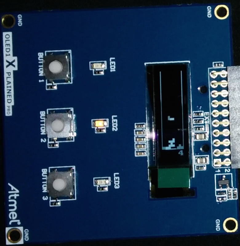
On a standard PC, a program interacts using the keyboard, the screen, the filesystem or the network. On that SAM4S Xplained Pro board, the program will get inputs via buttons, and it will produce visible effects by switching LEDs on and off and displaying patterns on the small OLED screen.
But there is no standard or predefined API for these devices. So we should write simple device drivers, starting with the simplest one: GPIO. GPIO is a common acronym used in the bare board world: General Purpose Input/Output. When configured as output, a GPIO pin can be commanded by a hardware register (in fact a variable mapped at a specific address) to emit current or not. On the board, four of them are interesting because they are connected to a LED. So if a 1 is written in a specific bit of the hardware register, the LED will be on and if a 0 is written it will be off. When configured as input, a GPIO register will reflect the value of a pin. Like for LEDs, four buttons are connected to a GPIO. So the application may read the status of a button from a register. A bit will be set to 1 when the button is pressed and set to 0 if not pressed.
The configuration of a GPIO device is highly device specific and we simply closely follow the vendor manual. First we need to power-up the device and enable its clock:
--  Enable clock for GPIO-A and GPIO-C

PMC.PMC_PCER0 := 2 ** PIOA_ID + 2 ** PIOC_ID;
Without that the device would be inactive. Technically, the LEDs and the buttons are connected to two different devices, GPIO-A and GPIO-C. Then we need to configure the port. Each bit in a GPIO word correspond to a GPIO pin. We need to configure pins for LEDs as output, and pins for buttons as input. We also need to enable that GPIO lines (there are more settings like pull-up or multi-driver, curious readers shall refer to the SAM4D data sheet):
--  Configure LEDs

PIOC.PER := Led_Pin_C + Led1_Pin_C + Led3_Pin_C
  + But2_Pin_C + But3_Pin_C;
PIOC.OER := Led_Pin_C + Led1_Pin_C + Led3_Pin_C;
PIOC.CODR := Led_Pin_C + Led1_Pin_C + Led3_Pin_C;
PIOC.MDDR := Led_Pin_C + Led1_Pin_C + Led3_Pin_C;
PIOC.PUER := But2_Pin_C + But3_Pin_C;
The device driver for a GPIO is often very simple. Here is a procedure that sets the state of LED 1:
procedure Set_Led1 (On : Boolean) is
begin
   if On then
      PIOC.CODR := Led1_Pin_C;
   else
      PIOC.SODR := Led1_Pin_C;
   end if;
end Set_Led1;
CODR means clear output data register; so any bit written as 1 will clear the corresponding bit in the output data register. Respectively, SODR means set output data register; so any bit written as 1 will set the corresponding bit in the output data register and bit written as 0 have no effect. This particular interface (one word to set and one to clear) is common and makes atomic bit manipulation easier.
The function to read the state of a button is also simple:
function Button3_Pressed return Boolean is
begin
   return (PIOC.PDSR and But3_Pin_C) = 0;
end Button3_Pressed;
We simply need to test a bit of the hardware register. Note that this is a low level driver. The code that calls this function must debounce the button. What does it mean? Real life is somewhat more complex than boolean logic. A button is a simple device with two pins. One is connected to power supply (here +3.0V) and the other is connected to the GPIO pin, but also to the ground via a resistor. When the button is not pressed, the voltage at the GPIO pin is 0V and the program will read 0 in the register. When the button is pressed, the voltage at the GPIO pin is +3.0V (well almost) and the program will read 1 in the register. But when the button is being pressed (this is not instantaneous), the voltage will increase irregularly from 0V to +3V, and due to capacity effects and non-uniformity of the button itself, the bit in the register will oscillate between 0 and 1 during a certain amount of time. If you don't take care, the application may consider a single push on the button as multiple pushes. Debouncing is avoiding that issue, and the simplest way to debounce is not reading the status again before a certain amount of time (like 20ms - but this depends on the button). We take care of that in the main loop of the Tetris game.
Developing a BSP for the Atmel SAM4S - OLED driver
Despite being very simple, the GPIO driver is a first good step. You can write simple applications to blink the LEDs or to switch the LEDs if a user presses a button. But LEDs and buttons are too simple for a Tetris game.
The SAM4S Xplained Pro has an OLED1 extension board. The OLED is a small screen and just behind it, there is a very small chip that controls the screen. This chip, the OLED controller, contains the bitmap that is displayed, refreshes periodically the screen, handles contrast, etc. These tasks are too complex to be performed by the CPU, hence the need for an OLED controller.
But this controller is somewhat complex. It communicates with the SAM4S using a dedicated interface, the SPI bus. SPI stands for Serial Peripheral Interface and as you can guess it uses a few lines (3 in fact) for a serial communication.
Let's have a closer look at the gory details. As you can suppose, we need to talk to the OLED controller whose reference is SSD1306. It accepts many commands, most of them to configure it (number of lines, number of columns, refresh rate) and some to change the bitmap (set the column or modify 8 pixels). All is done via the SPI so we need to first create an SPI driver for the SAM4S. Finally note that if commands can be sent to the OLED controller, that chip is not able to return any status.
The initialization of the SPI isn't particularly complex: we need to power on the device, and to configure the pins. In order to reduce the size of the chip and therefore its price, the SPI pins are multiplexed with GPIO pins. So we need to configure the pins so that they are used for SPI instead of GPIO. Here is an excerpt of the code for that (package Oled, procedure Oled_Configure):
--  Enable clock for SPI

PMC.PMC_PCER0 := PMC.PMC_PCER0 + 2 ** SPI_ID;

--  Configure SPI pins

PIOC.PER := Spi_DC_Pin_C + Spi_Reset_Pin_C;
PIOC.OER := Spi_DC_Pin_C + Spi_Reset_Pin_C;
PIOC.CODR := Spi_DC_Pin_C + Spi_Reset_Pin_C;
PIOC.MDDR := Spi_DC_Pin_C + Spi_Reset_Pin_C;
PIOC.PUER := Spi_DC_Pin_C + Spi_Reset_Pin_C;
Then there is a sequence to setup the SPI features: baud rate, number of bits per byte... We just have to read the Atmel documentation and set the right bits! (package Oled, procedure Spi_Init):
procedure Spi_Init is
   Baudrate : constant := 200; -- 120_000_000 / 5_000_000;
begin
   --  Reset SPI
   SPI.SPI_CR := SPI_CR.SWRST;

   --  Set mode register.
   --  Set master mode, disable mode fault, disable loopback, set chip
   --  select value, set fixed peripheral select, disable select decode.
   SPI.SPI_MR := (SPI.SPI_MR and not (SPI_MR.LLB or SPI_MR.PCS_Mask
                                        or SPI_MR.PS or SPI_MR.PCSDEC
                                        or SPI_MR.DLYBCS_Mask))
     or SPI_MR.MODFDIS or SPI_MR.MSTR or 0 * SPI_MR.DLYBCS;

   --  Set chip select register.
   SPI.SPI_CSR2 := 0 * SPI_CSR.DLYBCT or 0 * SPI_CSR.DLYBS
     or Baudrate * SPI_CSR.SCBR or (8 - 8) * SPI_CSR.BITS
     or SPI_CSR.CSAAT or 0 * SPI_CSR.CPOL or SPI_CSR.NCPHA;

   --  enable
   SPI.SPI_CR := SPI_CR.SPIEN;
end Spi_Init;
Now that the SPI interface is on, we need to configure the OLED controller. First action is to reset it so that it is in a known state. This is done via extra GPIO lines, and needs to follow a timing:
procedure Oled_Reset
is
   use Ada.Real_Time;
   Now : Time := Clock;
   Period_3us : constant Time_Span := Microseconds (3);
begin
   --  Lower reset
   PIOC.CODR := Spi_Reset_Pin_C;
   Now := Now + Period_3us;
   delay until Now;

   --  Raise reset
   PIOC.SODR := Spi_Reset_Pin_C;
   Now := Now + Period_3us;
   delay until Now;
end Oled_Reset;
Then we send the commands to configure the screen. That cannot be guessed and we'd better follow (again !) OLED controller manual:
procedure Ssd1306_Init is
begin
   --  1/32 duty
   Ssd1306_Cmd (SSD1306.CMD_SET_MULTIPLEX_RATIO);
   Ssd1306_Cmd (31);

   --  Set ram counter.
   Ssd1306_Cmd (SSD1306.CMD_SET_DISPLAY_OFFSET);
   Ssd1306_Cmd (0);

...
The OLED is now ready to use. The interface for it is rather low-level: we need to select the 'page' (which correspond to the line of the screen when oriented horizontally):
--  Set the current page (and clear column)
procedure Oled_Set_Page (Page : Unsigned_8);
And set pixels by groups of 8:
--  Draw 8 pixels at current position and increase position to the next
--  line.
procedure Oled_Draw (B : Unsigned_8);
Putting It All Together With Ravenscar
Most of the low-level work could be done (and was initially done) using the ZFP runtime of GNAT compiler. This runtime is very lightweight and doesn't offer tasking. But for bare boards, we have a better runtime called Ravenscar which provides the well-known Ravenscar subset of tasking features. We have already used it above for implementing delays, and we will also use it for the SPI driver. In the SPI driver, we need to send packet of bytes. We can send a new byte only when the previous one has been sent. With ZFP, we needed to poll until the byte was sent. But with Ravenscar, we can use interrupts and do something else (run another task) until the hardware triggers an interrupt to signal that the byte was sent. A protected type is declared to use interrupts:
protected Spi_Prot is
   pragma Interrupt_Priority (System.Interrupt_Priority'First);

   procedure Write_Byte (Cmd : Unsigned_8);

   procedure Interrupt;
   pragma Attach_Handler (Interrupt, Ada.Interrupts.Names.SPI_Interrupt);

   entry Wait_Tx;
private
   Tx_Done : Boolean := False;
end Spi_Prot;
The protected procedure 'Interrupt' is attached to the hardware interrupt via the pragma Attach_Handler, and the protected object is assigned to the highest priority via the pragma Interrupt_Priority (so that all interrupts are masked within the protected object to achieve exclusive access). The procedure Ssd1306_Write sends a command using the interrupt. It first programs the SPI device to send a byte and then waits for the interrupt:
procedure Ssd1306_Write (Cmd : Unsigned_8) is
begin
   Spi_Prot.Write_Byte (Cmd);

   Spi_Prot.Wait_Tx;
end Ssd1306_Write;
Writing a byte mostly consists of writing a hardware register (don't look at the PCS issue, that is an SPI low-level detail) and enabling SPI interrupts:
procedure Write_Byte (Cmd : Unsigned_8) is
begin
   --  Set PCS #2
   SPI.SPI_MR := (SPI.SPI_MR and not SPI_MR.PCS_Mask)
     or (SPI_MR.PCS_Mask and not ((2 ** 2) * SPI_MR.PCS));

   --  Write cmd
   SPI.SPI_TDR := Word (Cmd) * SPI_TDR.TD;

   --  Enable TXEMPTY interrupt.
   SPI.SPI_IER := SPI_SR.TXEMPTY;
end Write_Byte;
When the interrupt is triggered by the SPI device, the Interrupt procedure is called. It acknowledges the interrupt (by disabling it) and opens the entry (the Ssd1306_Write procedure is waiting on that entry):
procedure Interrupt is
begin
   if (SPI.SPI_SR and SPI_SR.TXEMPTY) /= 0 then
      --  Disable TXEMPTY interrupt
      SPI.SPI_IDR := SPI_SR.TXEMPTY;

      --  Set the barrier to True to open the entry
      Tx_Done := True;
   end if;
end Interrupt;
In the entry, we simply close the entry guard and clean the SPI state:
entry Wait_Tx when Tx_Done is
begin
   --  Set the barrier to False.
   Tx_Done := False;

   --  Deselect device
   SPI.SPI_MR := SPI.SPI_MR or SPI_MR.PCS_Mask;

   --  Last transfer
   SPI.SPI_CR := SPI_CR.LASTXFER;
end Wait_Tx;
Conclusion
You can see the results presented by our colleague Quentin at GNAT Pro Industrial User Day:


Overall, it was one week effort to produce this demo of SPARK on ARM. The code is available in the tetris.tgz archive attached if you're interested in experimenting with formal verification using SPARK or development in Ada for ARM. The source code is bundled with the complete development and verification environment for Linux and Windows in the archive at http://adaco.re/85.
To know more about SPARK:
- the SPARK User's Guide at http://docs.adacore.com/spark2014-docs/html/ug/index.html
- SPARK Pro page at www.adacore.com/sparkpro
To know more about GNAT for ARM:
- GNAT Pro for ARM page at http://www.adacore.com/gnatpro-safety-critical/
- GNAT GPL for ARM page at http://libre.adacore.com/tools/gnat-gpl-for-bare-board-arm
Some other people blogs show projects using GNAT on ARM.
- Mike Silva has great tutorials:
- Other very good tutorials by Jack Ganssle, Bill Wong and Jerry Petrey:
Attachments
- tetris - 9.13 kB
- tetris core - 5.26 kB
About Tristan Gingold

At AdaCore, Tristan Gingold works on the compiler backend, the debugger and the bareboard runtimes. He has ported the GNAT toolset to many new targets, including of course some ARM boards. Tristan Gingold holds an engineering degree from Ecole Nationale des Télécommunications and a DEA in microelectronics from Université Paris VI.
About Yannick Moy

Yannick Moy is Head of the Static Analysis Unit at AdaCore. Yannick contributes to the development of SPARK, a software source code analyzer aiming at verifying safety/security properties of programs. He frequently talks about SPARK in articles, conferences, classes and blogs (in particular blog.adacore.com). Yannick previously worked on source code analyzers for PolySpace (now The MathWorks) and at Université Paris-Sud.